Rectangular Profile
![]()
This function allows you to create a rectangular profile.
Access
- In the Designer tab, click the
 icon in the Wireframe section of the ribbon.
 - Activate the Wireframe tab and then click the icon in the Sketch section of the ribbon.
- Type rect in the Quick Search field and select Rectangle from the result list.
In all cases, this opens the Rectangle Options tab which is displayed along with the ribbon containing the Filters and Attributes sections.
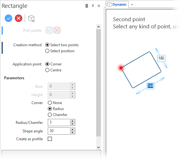
This also opens the Rectangle dialog box. ![]() (See dialog box.)
(See dialog box.)
Procedure
You can create a rectangle by picking two points in the graphic area or by selecting a position and using the dialog box parameters.
Point Selection
- Enable the Select two points option in the Creation method section of the dialog box.
- Select the Application point of the profile:
- Click on a point in the graphic area to define the application point of the profile.
- Click on a second point in the graphic area:
-
Validate, either by a Right Mouse click or by clicking the
 icon in the dialog box.
|
Corner Application Point |
Centre Application Point |
|
|
|
Position Selection
- Enable the Select position option in the Creation method section of the dialog box.
- Select the Application point of the profile:
- Click on a point in the graphic area to define the application point of the profile.
- Define the Base dimension:
- By dragging the Base arrow in the graphic area.
- By entering the value in the Base field in the graphic area or in the dialog box.
- By clicking on the Measurement
 icon, in the graphic area or in the dialog box (next to the active field), and taking measurements.
 - Define the Height:
- By dragging the Height arrow in the graphic area.
- By entering the value in the Height field in the graphic area or in the dialog box.
- By clicking on the Measurement icon, in the graphic area or in the dialog box (next to the active field), and taking measurements.
- Define the Shape angle to rotate the profile:
- By dragging the Shape angle arrow in the graphic area.
- By entering the value in the Shape angle field in the graphic area or in the dialog box.
- By clicking on the Measurement icon, in the graphic area or in the dialog box (next to the active field), and taking measurements.
-
Validate, either by a Right Mouse click or by clicking the
icon in the graphic area or in the function dialog box. - Base
- Height
- Shape angle
![]() Note:
Note:
Once a Shape angle has been defined, it is automatically applied to all subsequent rectangle creation operations.
|
|
Creating a Radiused or Chamfered Rectangle
- Select the Point selection or Position selection method.
- Select the Radius or Chamfer option in the Corner section of the dialog box.
- Define the radius/chamfer value:
- By entering value in the field below these 2 options.
- By clicking on the Measurement icon, in the graphic area or in the dialog box (next to the active field), and taking measurements.
- By clicking and dragging the radius/chamfer arrow in the graphic area or entering a value in the adjacent arrow input field.
-
Validate, either by a Right Mouse click or by clicking the
icon in the dialog box.
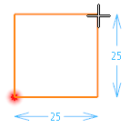
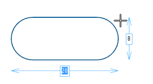
Example of a radiused rectangle created by selecting two points:
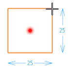
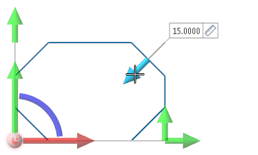
Example of a chamfered rectangle created by selecting a position:
Create as profile
Activate the Create as profile option if you want the rectangle to be created as a profile for extrusion purposes.
![]() Notes:
Notes:
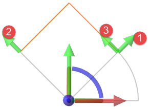
- Drag the green, red and/or blue arrows of the Workplane Axis Marker to translate the profile in the graphic area.
- Drag the green, red and/or blue arc of the Workplane Axis Marker to rotate the profile in the graphic area.
- Drag the sphere of the Workplane Axis Marker to move the profile in the graphic area.
-
You can use simple JavaScript expressions and mathematical formulas to define the required values.
-
The label of the corresponding Slider element is displayed when holding the mouse cursor over it or if you click it.
- Use the Attributes toolbox to modify the created entities.
-
Sketch plane creation may be automatic.
- You can lock the dimension labels.
Dialog Box Options
Top Toolbar
![]()
![]()
![]()
These two icons at the top of the dialog box allow you to Apply the current values or to Cancel the current function.
Preview generation is Automatic if this option is active in the dialog box menu accessed by clicking on the  icon. If this option is not active, click on the
 ![]() icon. If preview generation is not possible, the icon is greyed out.
icon. If preview generation is not possible, the icon is greyed out.
Pick points
Clicking on the ![]()
![]()
Information Field
The field at the bottom of the dialog box displays information about missing data, errors or actions.